Power Electronics Lab

During the fall semester of my junior year, I took 6.131/6.2220 (Power Electronics Lab) taught my Professor Steve Leeb. Throughout the class, we covered ways to step-up and down voltage between DC-DC, AC-AC, DC-AC, and AC-DC. 

Fluorescent Lamp Ballast
 I designed and built a resonant converter that steps up 40V to 400V to strike a fluorescent lamp ballast and sustain sustain operation during steady state. The project involved developing the full control circuitry, such as a PWM generator, delay circuitry, totem pole driver and the L-C resonant network. 
 

To select appropriate MOSFETs and diodes, I analyzed device datasheets to ensure sufficient voltage headroom and performed calculations on switching frequency, power dissipation, and efficiency.

For the resonant circuit, I wrote a custom script to generate Bode plots of the transfer function across varying capacitor values, helping visualize the system’s frequency response. I also evaluated several inductor cores by comparing their saturation characteristics and equivalent series resistance (ESR), ultimately selecting a ferrite core for its superior efficiency and lower impedance compared to micrometal alternatives.

Screenshot 2025-11-07 at 11.48.43 PM

After building the circuit and lots of debugging, it was really reward to see the lamp light up! I captured oscilloscope waveforms of the voltage across the lamp during striking, which shows how the voltage builds up as the circuit reaches resonance before settling into steady-state operation.

Screenshot 2025-11-08 at 12.03.06 AM
Screenshot 2025-11-08 at 12.05.15 AM
200V DC Power Supply 

We also designed a 200 V power supply from a 24 V input using a flyback converter capable of delivering 2 W. I developed the control circuitry and selected the appropriate semiconductor components to meet the voltage and power requirements. I also chose a ferrite core to achieve the desired turns ratio, minimized parasitic capacitance, and ensured operation in continuous conduction mode (CCM) for improved efficiency and stability.

Screenshot 2025-11-08 at 12.12.46 AM
DC Motor and 3 Phase Inverter

I also designed and built a custom DC motor, optimizing the rotor design and number of windings to maximize rotational speed (RPM). In addition, I developed a three-phase bridge, PWM control circuitry, and a finite state machine to drive a three-phase inverter for an induction motor.

Variable Speed Drive for an Electric Go-Cart 

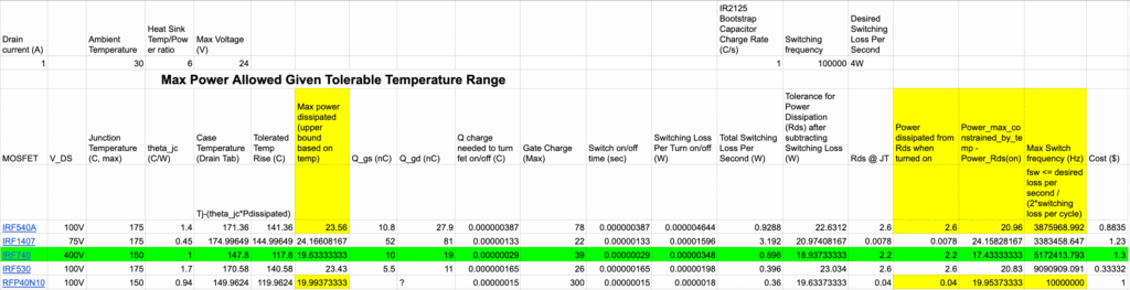
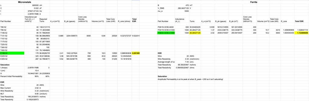
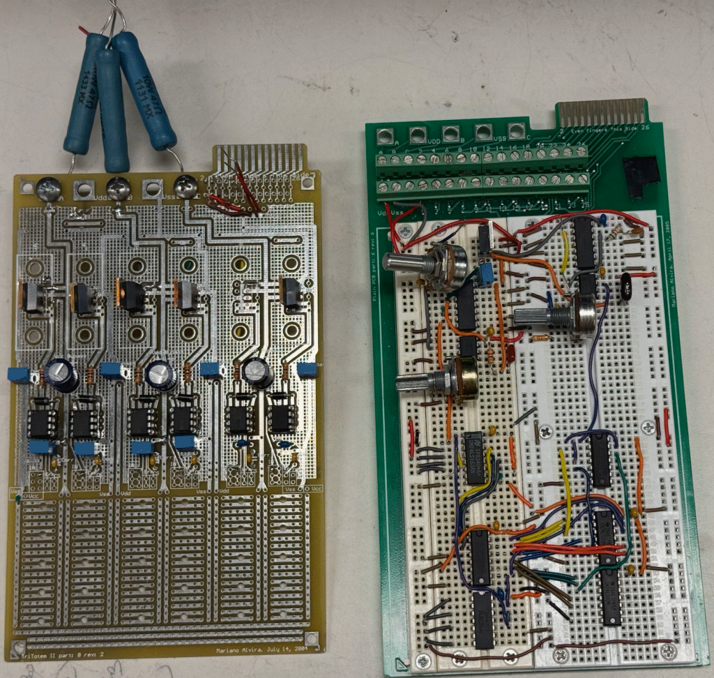
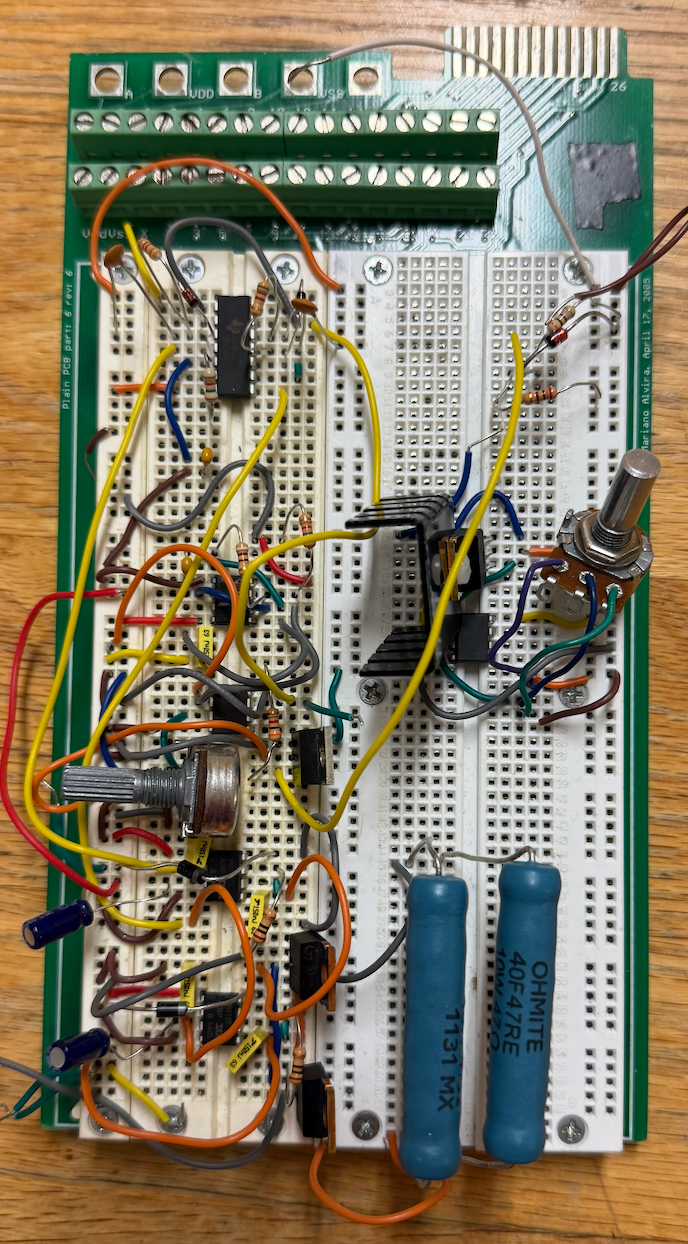
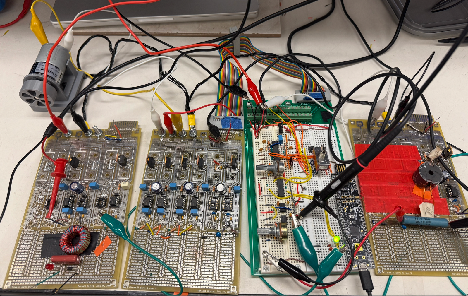
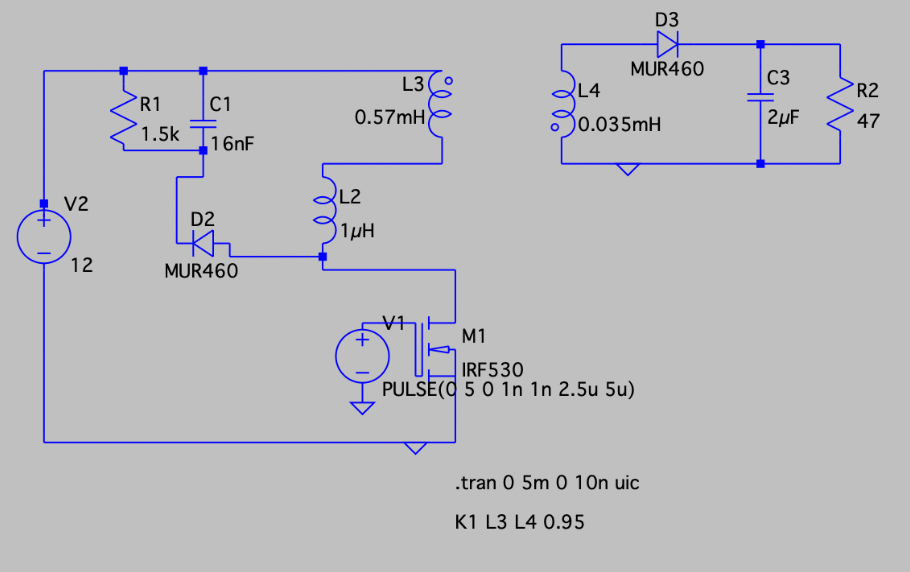
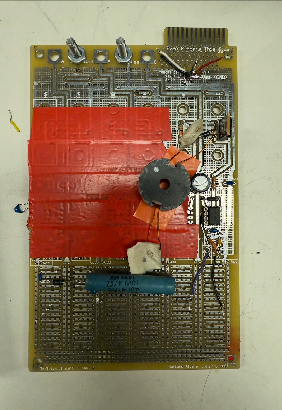
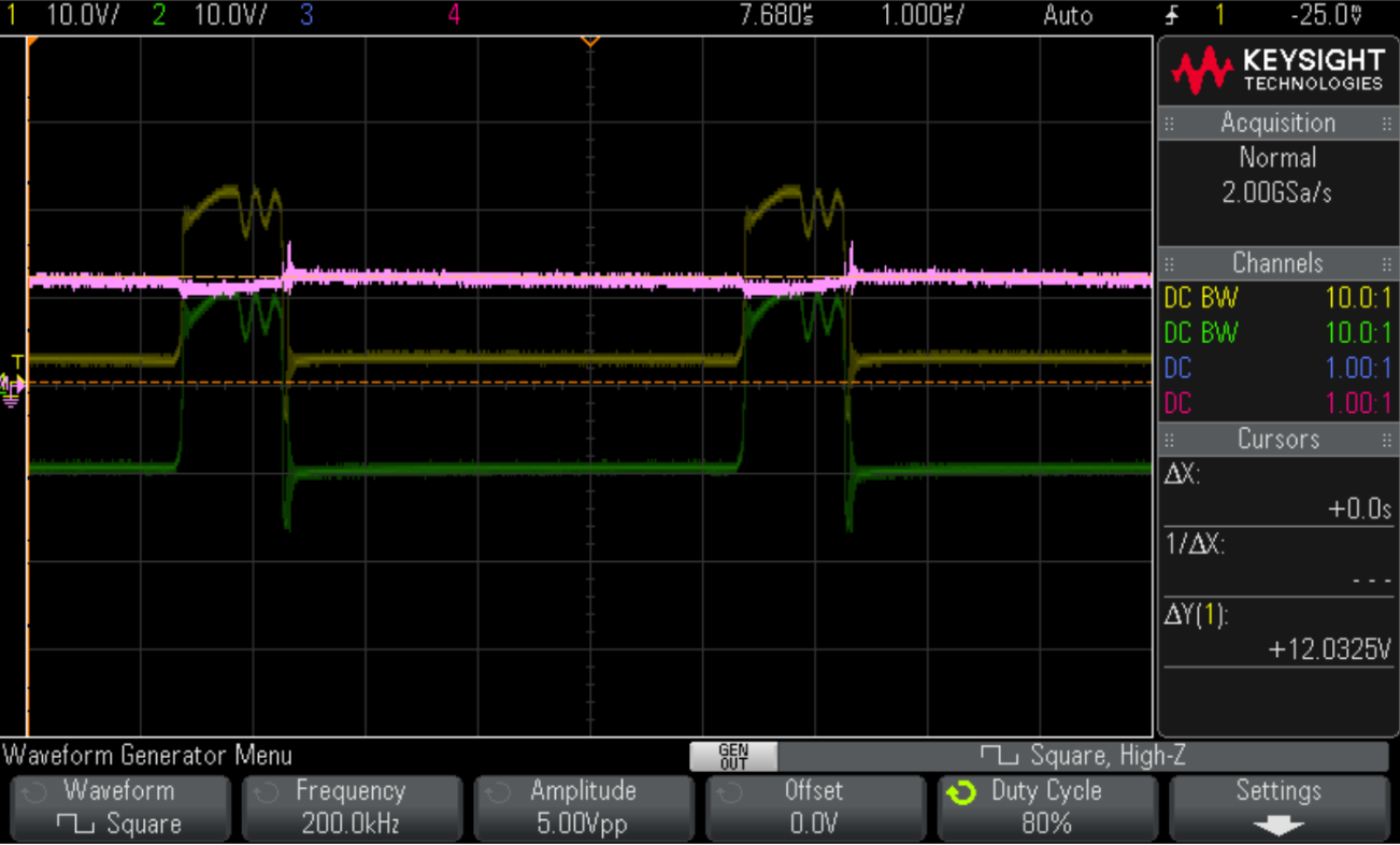
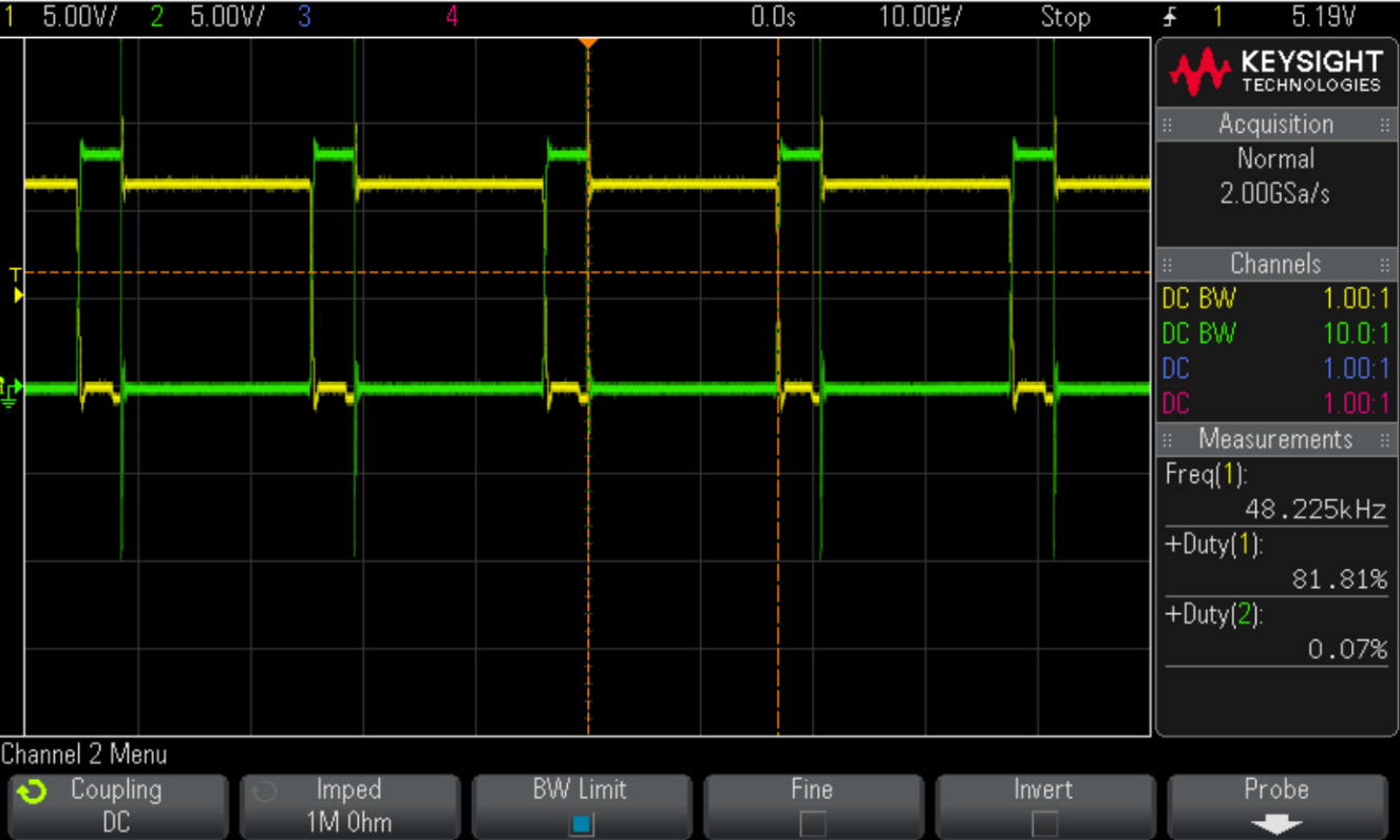
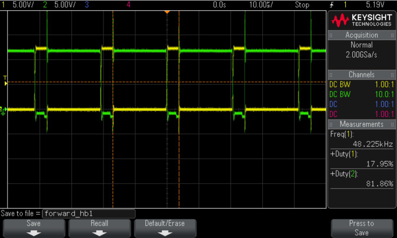
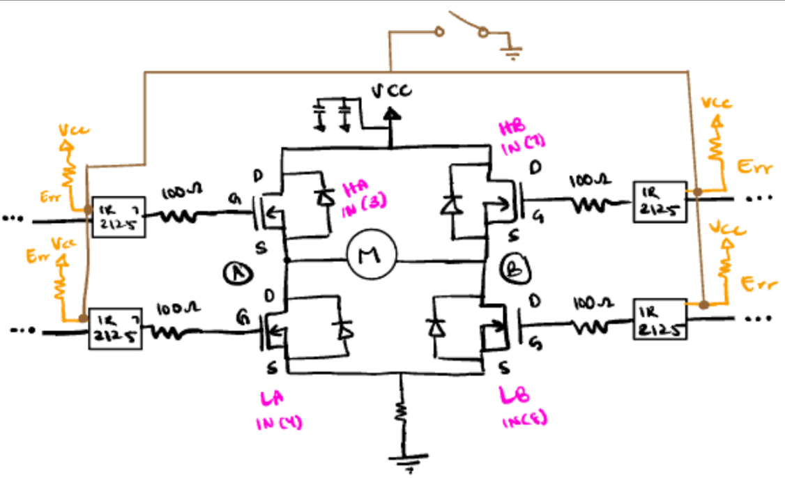
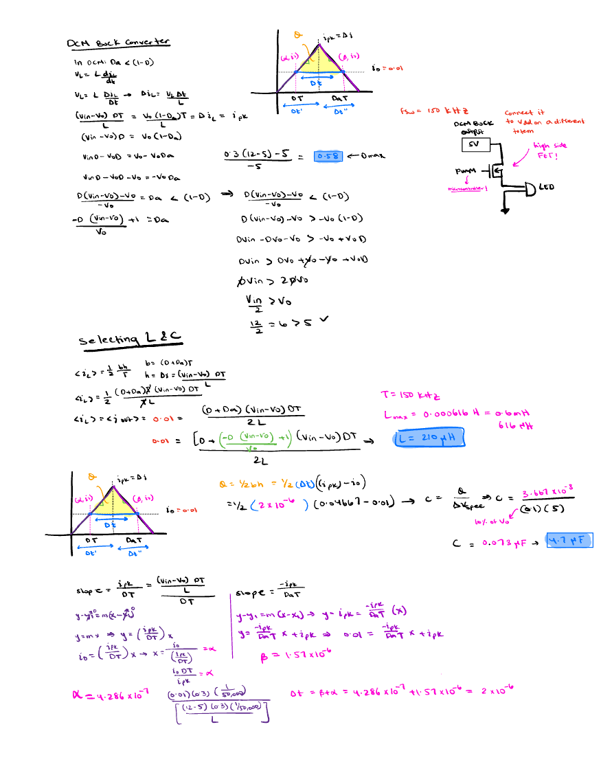
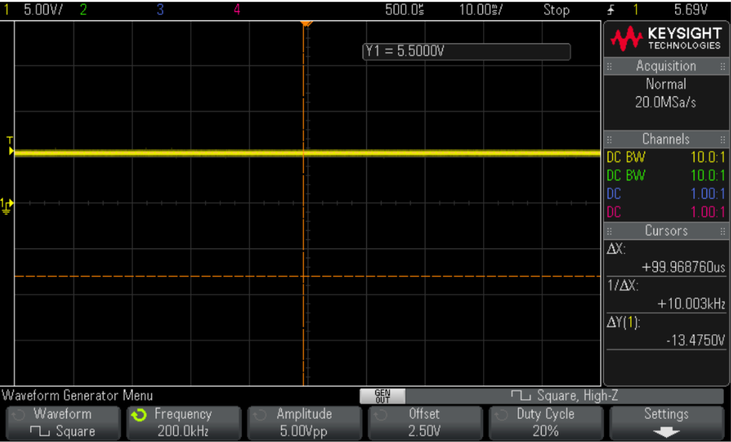
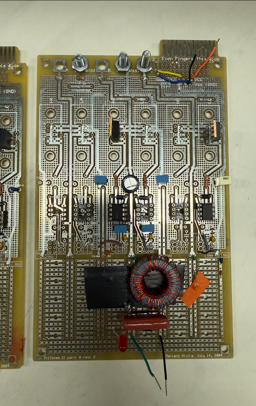
We designed the power electronic drive for an electric go-kart, consisting of a clock ramp, PWM generator, delay circuitry, and a totem-pole driver with a “turn-on” switch. In addition, L–C network acted as a low-pass filter to remove AC components and smooth the output voltage for stable motor operation.

Screenshot 2025-11-08 at 12.27.24 AM
Class D Stereo Amplifier 

I designed and built cascading DC-DC converters to power a 12 W stereo amplifier operating from four 1.5 V batteries. The system included a buck converter, a boost converter, and two totem amplifiers to deliver efficient power conversion in a compact form. I carefully selected the L and C components to maintain continuous conduction mode (CCM) and meet the output voltage ripple requirements.

This was one of the earlier labs I completed and looking back, it’s a great reminder of how much my circuit design and breadboarding skills have improved since then!

Final Project

For my final project, I created a go-cart drive and safety lights driven by my interest in electric vehicles. This included creating a flyback converter that drives an H-Bridge driver circuit to control a DC motor and a DCM buck converter to power LEDs. The LEDs illuminate during braking and flash when the motor operates in reverse. Here is my final project proposal.

Flyback Converter – Objectives:
  • Input Voltage: 12V
  • Output Voltage: ~0-12V
  • Switching Frequency: 200 kHz
  • Max Output Power: 2.4 W
  • Voltage Ripple: 10% of Vout 
  • Lleak = 1% of Lmag
  • Operates in CCM
  • Voltage across clamp = 2.5 * Vout 

First, I began by designing the flyback converter which would convert 12V to around 0-12V to power a DC motor that handles a maximum of 12V, draws 0.2A and has a terminal resistance of 60 Ω. I validated my calculation using LTSpice and decided to use a P26/16 Ferrite core with 28 turns and a turn ratio of 4:1. For the semiconductors, I used an IRF540 and a MUR120 for minimal switching losses and to handle the voltage. 

I built the flyback converter and captured scope shots of the results. At 50% and 80% duty cycle, the flyback converter outputs 3V and 12V, respectively as expected. 

H-Bridge – Objectives:
  • Include a “rock-on” to allow motor to brake 
  • Include a switch capable of switching between “forward” and “reverse”
  • Switching Frequency: 50 kHz with a 1μ second delay
  • Adjustable PWM 

In order for the motor to spin “forward”, I feed DELAY into the MOSFET drivers that are diagonal from one another, namely HA and LB. Since the high side FET won’t turn on unless the low side FET is turned on first, I feed DELAY bar into LA so that the bootstrap capacitor of HA can sufficiently charge. Then, I tie GND to HB. 

While testing the H-Bridge, I ran into several challenges with shoot through due to capacitative coupling, floating nodes and noise. I was able to resolve these issues after grounding the inputs for unused gate drivers and increasing the duty cycle of DELAY to around 75%. I used a 4PDT (4 Pole, Double Throw) Switch, which I routed my control circuitry signals to and connected to HA, LA, HB, LB to switch between “forward” and “reverse”. I also implemented a push button that tied the floating error pins of the IR2125s to ground when pressed, acting as the “rock on” switch.

I took scope shots of the output voltage at the motor’s terminals in the two modes.  

DCM Buck Converter – Objectives:
  • Input Voltage: 12v
  • Output Voltage: 5V
  • Switching Frequency: 150 kHz (Wave Gen)
  • Voltage Ripple: 10% of Output Voltage 

Upon performing calculations, I decided to use a T131-52 Core with 44 turns. I chose to operate at a Duty Cycle of around 20% to remain in DCM and observed an output voltage of around 5V (good enough for the LEDs). 

Integration

I connected the output of the flyback converter to the rail of the H-Bridge. I programmed a  PSOC (microcontroller) to control the logic for the lights, connecting HA and the Error pin of the IR2125 to inputs on the PSOC. When the Error pin is pulled high, the motor is in “braking” mode so a 1 kHz 50% Duty Cycle square wave is outputted to the IR2125 of the LED driver. When HA and the Error pin are pulled low, the motor is accelerating in “reverse” mode, prompting the PSOC to output a 3Hz square wave. The 5V output of the DCM buck converter is connected to the drain of a high side MOSFET. The source of the MOSFET is connected to the anode of the LED, and the cathode is connected to ground. The frequency of the PWM sent to the gate, determines whether the LED shines or flashes.  After cleaning up my circuitry, here was the final result!